Clean-water plumbing must be installed as a coordinated system with structural, architectural, electrical, and sanitary works. Incorrect routing, defective joints, or undocumented testing can cause concealed leakage, damage to finishes, water contamination, and rework. This SOP provides a field-ready sequence for installing residential clean-water pipework and completing hydrostatic pressure testing before concealment or handover.
Use this SOP with the latest approved drawings, technical specifications, shop drawings, MEP method statement, manufacturer instructions, and applicable local requirements. Where documents conflict, the contract documents and written direction of the authorized project representative govern.
1. Purpose and scope
The purpose is to ensure that the clean-water system is installed to design, uses traceable materials, has watertight joints, is protected from damage, and has test results acceptable before concealment or use.
The scope includes material receipt; route, level, and penetration verification; pipe and fitting installation; supports and protection; jointing; flushing; hydrostatic pressure testing; inspection hold points; nonconformance control; cleaning; records; and handover. The system may extend from the source or tank to fixtures, valves, and outlets as shown on the approved drawings.
2. References and document control
- Approved IFC or construction drawings, including riser, shaft, sleeve, and penetration details.
- Project specifications, material submittals, method statements, and approved product or manufacturer schedules.
- Manufacturer instructions covering installation, pressure limits, curing time, jointing, storage, and commissioning.
- Applicable building, environmental health, potable-water, and occupational safety requirements for the location.
- Inspection forms, permits, pressure-test checklists, as-built drawings, and change-control procedures.
The supervisor shall ensure that only current document revisions are available at the workface. Any change to routing, diameter, material, or valve location must be recorded through a revised drawing or written instruction before installation. Inspection and test records shall identify the area, date, system number, test instruments, and inspecting parties.
3. Roles and competency
- Construction or site manager: provides resources, resolves multidisciplinary interfaces, and approves the test plan.
- Plumbing supervisor: converts drawings into a work sequence, checks materials, controls the workforce, and calls the required hold points.
- Installer or technician: cuts, fits, joins, and tests pipework in accordance with training for the selected pipe system. No technician may use an unfamiliar jointing method.
- QC inspector: independently verifies materials, installation, pressure testing, instrument calibration, and punch-list closure.
- HSE officer: assesses risks and verifies permits, barricades, PPE, and pressure-release controls.
- Client or consultant: attends witness or hold points where required and accepts the test records.
4. Materials, tools, and receiving controls
Use pipe, fittings, valves, seals, adhesive, gaskets, clamps, sleeves, supports, and accessories approved for clean-water service and compatible with one another. Materials should carry size, class or rating where relevant, batch identification where available, and approval documentation. Do not combine components from different jointing systems without technical approval.
On delivery, check quantity, size, damage, deformation, cracks, contamination, pipe ends, and fitting completeness. Store pipe on level supports, protected from excessive heat and impact, with the ends capped. Store adhesive, sealant, and gaskets according to the manufacturer’s instructions and do not use expired products. Cutting tools, deburring tools, torque tools, test pumps, pressure gauges, and other instruments must be serviceable. Test gauges shall have valid calibration and a suitable measurement range.
5. Initial inspection and work-area preparation
- Review the drawings, specifications, fixture details, flow direction, valve locations, drain points, and test-zone limits.
- Coordinate routes with beams, columns, reinforcement, ductwork, cable trays, waterproofing, ceilings, cabinets, and maintenance access. Do not cut structural elements without written approval.
- Verify that sleeves, openings, shafts, and penetrations are available or marked. Install sleeves and fire- or waterproof sealing in accordance with approved details.
- Ensure the area is adequately lit, safe, and free of standing water, with access for cutting, jointing, filling, venting, draining, and inspection.
- Identify each test section. Isolate equipment that is not designed to receive the test pressure using approved valves, blinds, or another approved method.
6. Routing, gradients, and supports
Install pipework to the coordinates, elevations, slopes, and clearances shown on the drawings. Routes shall be neat, serviceable, and free from unintended air pockets or low points without drainage. Pipes passing through walls or floors shall not bear directly against penetration edges; use the specified sleeve, insulation, or protection.
Install supports, hangers, clamps, anchors, and guides at the approved spacing and type for the pipe material and size. Supports must not hang from other pipes or from elements not designed to carry the load. Allow for expansion, contraction, thermal movement, and valve access. Do not tighten clamps enough to crush or distort the pipe. For embedded pipe, protect it from nails, screws, abrasion, chemicals, and construction loads, and record its position before concealment.
7. Cutting and jointing
- Measure and mark pipe from the drawings and verified site conditions. Cut square with the correct tool, then deburr and clean the surfaces.
- Check insertion depth, fitting orientation, gasket or thread condition, and component compatibility before making the joint.
- For solvent cement, fusion, press, compression, threaded, grooved, or other methods, follow the manufacturer’s sequence for cleanliness, temperature, heating, pressure, curing, and dedicated tools. Do not load, twist, or test a joint before the required curing period has elapsed.
- For threaded joints, use compatible sealant and avoid over-tightening. For gasketed joints, ensure the gasket is clean and evenly seated; tighten bolts in sequence where applicable.
- Cap open pipe ends whenever work stops to prevent dust, mortar, insects, or foreign matter entering. Remove adhesive residue and label routes or valves.
Misaligned, cracked, contaminated, insufficiently inserted, overheated, or deformed joints shall be cut out and remade. Do not stop a leak by applying external adhesive, sealant, or extra wrapping as a substitute for a correct joint.
8. Flushing before testing and use
When the section is ready and all joints have cured sufficiently, inspect the interior as far as practical and flush with clean water. Open a drain or outlet at a safe location and flow water from the inlet until the discharge is reasonably clear and free of construction debris. Flushing shall follow the project specification or applicable authority requirements. Discharge must not damage finishes, flood rooms, or create a hazard.
After flushing, reinstall strainers, aerators, cartridges, or other removed components where required. If the system will serve potable water, carry out cleaning or disinfection in accordance with applicable requirements and the direction of the responsible authority. Record the water source, section, time, outlet condition, and any follow-up action.
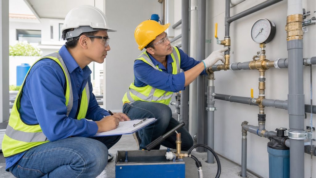
9. Hydrostatic pressure-test method
- Define the test limits, test pack, fill point, vents, drains, isolation valves, and components to be removed or protected.
- Ensure all joints to be inspected remain exposed. Do not permanently close pipework, install permanent insulation, or close shafts before the inspection hold point is released unless written approval has been issued.
- Fill the system slowly from a low point with clean water. Open vents at high points to remove air. Trapped air can produce unstable readings and increase the hazard when pressure is released.
- Raise pressure gradually with a suitable test pump to the test pressure stated in the specification, drawings, or approved manufacturer instructions. Never exceed the rating of the weakest component.
- Stabilize the system for the specified period. Visually inspect every joint, valve, fitting, penetration, and fixture connection. Monitor the reference gauge and an additional gauge where necessary.
- Accept or reject the result against the approved criteria. If the test fails, release pressure slowly, identify the cause, repair it, and retest after the required curing or reinspection.
- After acceptance, release pressure to a safe location, drain or refill as planned, remove temporary blinds, and restore the system configuration.
Acceptance criteria
- Test pressure, stabilization period, observation duration, and permitted pressure loss shall follow the project specification, applicable requirement, or approved manufacturer instruction. They must not be set only by field habit.
- There shall be no leakage, seepage, dripping, cracking, movement, deformation, or damage to pipe, fittings, valves, supports, or penetrations.
- Gauge readings shall remain within the permitted limit after allowing for temperature stabilization and test conditions. Any water addition or pressure adjustment must be recorded and approved.
- The section, instruments, initial and final pressure, times, relevant area conditions, inspection result, and signatures of the involved parties shall be complete and traceable.
10. Hold points and inspections
| Stage | Control and evidence | Status |
|---|---|---|
| Material receipt | Submittal, identification, size, condition, and storage are checked. | Release for installation |
| Before concealment | Routing, supports, sleeves, joints, valves, clearances, and pre-closeout photographs are checked. | Hold point |
| Before pressure test | Section is isolated, vents and drains are available, gauge is calibrated, and joints are exposed. | Witness or hold point |
| After pressure test | Test form, punch list, repairs, and retest are closed. | Release for concealment |
| Before handover | Flushing, labels, valve access, as-builts, manuals, and spare parts are verified. | Acceptance |
11. Nonconformance and rework
Nonconformances include unapproved material, incorrect routing, inadequate support, failed joints, contaminated pipe, pressure-test failure, or incomplete records. QC shall issue a nonconformance report or punch item describing the location, evidence, impact, corrective action, responsible party, and due date.
The supervisor shall isolate the area and keep the defect visible. A repair method shall be submitted where required. After repair, perform visual inspection and retest the affected section or the complete section as directed by QC. Do not remove failure indicators, alter gauge results, or close work without written release.
12. Safety requirements
- Conduct a toolbox talk and risk assessment before work. Wear a hard hat, safety footwear, gloves, eye protection, and task-specific PPE.
- Barricade the pressure-test area and restrict access. Never stand in front of an end cap, blind, plug, or joint while pressure is being raised.
- Inspect hoses, pumps, temporary fittings, anchors, and gauges before use. Raise and release pressure in a controlled manner; never open a pressurized joint.
- Provide ventilation and ignition control when using adhesive or chemicals. Follow the safety data sheet and avoid skin contact or vapor inhalation.
- Secure cables and hoses away from walkways. Control discharge water, work at height, shaft access, and slip hazards.
- Coordinate with electrical and structural teams. Do not drill, cut, or form penetrations without checking concealed services and obtaining permission.
13. Records and handover checklist
The quality dossier should include the drawings and revisions used, material approvals, delivery records, certificates or technical data, installation checklists, pre-closeout photographs, gauge calibration certificates, pressure-test packs, flushing or disinfection records where applicable, NCRs and closeout evidence, change records, and as-built drawings.
The handover checklist shall verify that all valves are labelled and operable, drains and service access are available, fixtures are protected and clean, penetrations are sealed, there is no visible leakage, tests are accepted, the area is clean, and the operator has received operation and maintenance instructions. The Checklist Audit Plumbing & Sanitasi Rumah may be used as an additional room-by-room review, while Metode Pelaksanaan Pekerjaan MEP can help coordinate interfaces and work sequencing.
14. Common failures and prevention
- Pressure loss caused by trapped air: fill from low points, open vents, and stabilize temperature before recording the result.
- Leaking joints: control cleanliness, insertion depth, curing, torque, and tools for the selected joint type.
- Pipe damaged after passing the test: protect pipework from follow-on trades and reinspect before concealment.
- Incorrect or unserviceable route: coordinate overlays or BIM information, mark the workface, and verify access before installation.
- Internal contamination: cap pipe ends, store materials correctly, flush thoroughly, and never place pipe directly on dirty ground.
- Unreliable test evidence: complete the form, use calibrated gauges, identify the test section, and obtain the planned witness signatures.
Conclusion
An acceptable plumbing installation is more than pipework in place. It is a documented system that matches the approved design, is protected and serviceable, is clean and watertight, and has traceable inspection evidence. The essential controls are material verification, coordinated routing, sound jointing, flushing, hydrostatic testing against approved requirements, and strict hold-point discipline before concealment.
FAQs
May pipework be tested after it has been plastered over?
It should not be the normal practice. Test and inspect while joints remain visible. Concealment should follow acceptance, or written approval for a specific exceptional condition.
What pressure and duration should be used?
Use the pressure and duration stated in the project specification, applicable requirements, or approved manufacturer instructions. Do not apply a generic value that could exceed a component rating or conflict with the contract documents.
Does every pressure drop mean the pipe is leaking?
No. Trapped air, temperature change, pipe elasticity, or initial stabilization can affect readings. The system must nevertheless be inspected, and acceptance is allowed only when the approved limit is met and no leakage is observed.
When should flushing be performed?
Flush after joints have cured sufficiently and before the system is placed in service. Flush again if later construction work could have introduced dust or foreign matter.
Who releases pipework for concealment?
The project inspection and test plan governs. It normally involves the supervisor and QC, with client or consultant witness where required.
What should be done when a pressure test fails?
Release pressure safely, record the location and probable cause, repair using an approved method, reinspect, then repeat the pressure test and document the result.