A residential electrical installation must be treated as a safety system, not simply as a task of pulling cables and fitting accessories. Errors in circuit identification, connections, earthing, or protective devices can cause electric shock, equipment damage, overheating, and fire. This SOP provides a practical workflow for contractors, supervisors, electricians, and homeowners from preparation through handover.
This is a general execution guide. The final installation must comply with approved drawings, actual loads, equipment specifications, the electricity utility’s requirements, and the regulations and standards applicable at the project location.
1. Purpose and scope
The purpose of this SOP is to ensure that the installation is built to the design, safe to operate, inspectable, and supported by complete test records. The scope includes the main and distribution boards, incoming supply, conductors, conduit, junction boxes, switches, socket outlets, lighting points, earthing system, protective devices, testing, and handover.
It applies to new installations, additional circuits, renovations, and replacement of components in dwellings. Utility-network work, generation, solar and battery systems, electric-vehicle charging, and other special systems require additional procedures from the designer or a competent specialist.
2. Terms and references
- DB or distribution board: an enclosure for isolation, circuit distribution, and protection.
- MCB: a protective device for overload and short-circuit conditions on a circuit.
- RCD/RCBO: a device that detects residual current to earth; an RCBO combines residual-current and overcurrent protection.
- PE: protective or earthing conductor. N: neutral conductor. L: line or live conductor.
- Hold point: a stage that cannot be covered or continued until inspection and approval are complete.
- As-built: drawings and data representing the installation as actually constructed.
Minimum references include approved drawings and specifications, the electricity utility’s requirements, occupational safety rules, PUIL/SNI or the adopted electrical standards in force for the project location, and manufacturer installation instructions. Use the edition required by the authority or contract; do not replace design requirements with an installer’s assumption.
3. Roles, competence, and responsibilities
- Owner or owner’s representative: approves load requirements, point locations, design changes, and planned power shutdowns.
- Designer or engineer: defines circuit distribution, conductor sizes, protective-device ratings, earthing method, and testing requirements.
- Electrical supervisor: checks materials, coordinates the work, controls hold points, and ensures records are complete.
- Electrician: installs and tests to the design, uses serviceable tools, and reports nonconforming conditions.
- Safety officer: controls energy isolation, access, PPE, work at height, and emergency response.
- Inspector or construction supervisor: verifies quality, witnesses required tests, and closes findings.
Live work, testing, and connection to the supply must be performed only by personnel with the competence and authorization required by local regulations. Workers must understand the single-line diagram, conductor identification, test equipment, and lockout/tagout procedure.
4. Inputs, materials, and approvals before starting
Required documents
- Electrical point layouts, single-line diagram, panel schedule, and earthing details.
- Load schedule and the basis for selecting conductor, conduit, and protective-device sizes.
- Material specifications, required certificates or evidence of conformity, and manufacturer data.
- Inspection and test plan, checklists, and change-control procedure.
Material inspection
Confirm that cables have the correct type, cross-sectional area, and rating; that conduit, boxes, glands, lugs, terminals, and accessories are compatible; and that the panel has adequate space and rating. Check MCBs, RCDs, or RCBOs against the design. Inspect for physical damage, moisture, unreadable markings, broken seals, and tool calibration status. Damaged or nonconforming materials must be quarantined.
Before concealed work starts, the supervisor must approve the shop drawing, routes, penetrations, coordination with structure and plumbing, and panel locations. Changes must be approved in writing before installation.
5. Installation sequence
5.1 Preparation and setting out
- Review the drawings, survey the site, and mark the panel, lighting points, switches, socket outlets, conduit routes, and earthing electrode location.
- Confirm heights, door swings, fixed furniture, wet areas, pipe routes, and structural elements.
- Identify existing energy sources. Apply isolation, locking, tagging, and prove dead before demolition or connection.
5.2 Conduit and box installation
- Install conduit on orderly routes, with bends that do not damage cables, adequate supports, and reasonable pulling access.
- Use accessible junction boxes. Do not bury connections in plaster, concrete, or inaccessible voids.
- Protect conduit ends from sharp edges and temporarily keep them free from mortar and water. Separate power from communications or special systems as required by the design.
- Inspect coordination before concrete placement, wall closure, or ceiling installation. This is the concealed-installation hold point.
5.3 Cable pulling and termination
- Ensure conduit is clean and unobstructed. Pull cables without damaging insulation and without exceeding the manufacturer’s pulling tension or bending radius.
- Maintain consistent identification of L, N, and PE. Never use the protective-conductor color for another function.
- Leave sufficient cable for neat termination. Avoid connections outside boxes and do not place two conductors in a terminal not designed for them.
- Tighten terminals to manufacturer instructions. Where required, use a torque tool and record the result.
- Cap unused cable ends, install correct glands or bushings, and preserve the enclosure’s required degree of protection.
5.4 Panel assembly and protective devices
- Install the panel upright, securely, accessibly, and with safe working space. Provide durable, legible circuit labels.
- Connect incoming conductors, busbars, MCBs, RCDs/RCBOs, neutral, and PE in accordance with the diagram. Neutrals protected by an RCD must not be mixed with another circuit’s neutral.
- Verify panel earthing and PE continuity. Do not rely on metal conduit as the sole protective path unless it is designed and permitted for that purpose.
- Fit covers, blanking plates, and touch protection. No energized part may be accessible during normal use.
5.5 Accessories and equipment
Install switches, socket outlets, light fittings, exhaust fans, water heaters, pumps, and other equipment to their ratings and manufacturer instructions. Wet areas require location, protection, and additional devices appropriate to the approved design and local rules. Ensure plates are level, screws do not damage devices, and cables are not pinched.
6. Inspections and hold points
| Stage | Key control | Evidence or decision |
|---|---|---|
| Before installation | Drawings, materials, tools, competence, and energy isolation are approved. | Preparation checklist and start approval. |
| Before concealment | Conduit routes, boxes, conductor sizes, separation, and access to connections are checked. | Photos, checklist, and hold-point release. |
| Before energization | Terminations, labels, covers, earthing, and removal of tools are verified. | Pre-energization checklist and energization permit. |
| After testing | Results meet the design, findings are closed, and changes are recorded. | Test report and acceptance record. |
7. Testing and acceptance criteria
Testing must be performed by competent personnel using suitable equipment with current calibration status. Isolate equipment that could be damaged by the test voltage. Limits must follow PUIL/SNI or the applicable standard, the design, and manufacturer instructions. Record the method, test points, conditions, instrument, results, and tester identity.
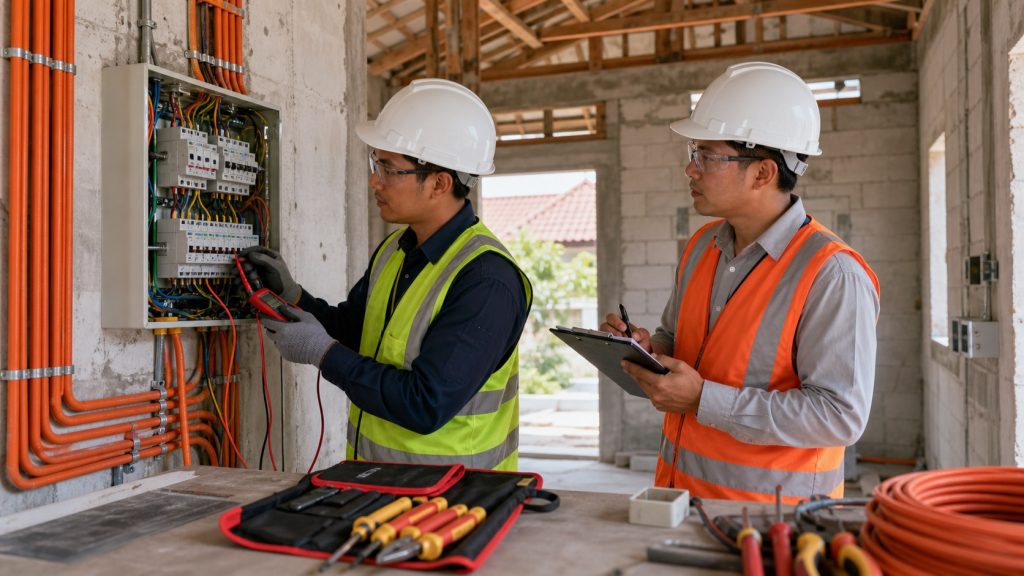
- Visual inspection: panels, accessories, labels, marked polarity, touch protection, routes, and cable condition must match the drawings and be free from damage.
- PE continuity: the protective path must be continuous from the earthing bar or source point to every required point. There must be no loose connection or open path.
- Conductor continuity: live and neutral conductors are checked for continuity and correct circuit association.
- Insulation resistance: test between live conductors and to PE at the voltage and minimum limit required by the applicable standard. Disconnect sensitive electronic equipment before testing.
- Polarity: switches must interrupt the specified conductor, line and neutral terminals must not be reversed, and socket outlets must follow the approved configuration.
- Earthing: continuity, connections, and electrode resistance, where required, must comply with the design and local requirements.
- RCD/RCBO: use the test button and instrument testing according to the device test schedule. Trip current or time must be within the manufacturer’s and applicable standard’s limits.
- Functional test: each switch, light, socket outlet, fan, and appliance is operated under normal conditions without abnormal heating, noise, odor, or nuisance tripping.
Do not declare an installation compliant merely because a light turns on. Any failed criterion must be recorded as a nonconformance and corrected before energization or handover.
8. Safety requirements
- Prefer dead working. Isolate the source, lock it, tag it, discharge stored energy, and verify absence of voltage with a proven tester.
- Use PPE appropriate to the hazard: helmet, safety footwear, eye protection, suitable gloves, and additional protection for special tasks. Gloves do not replace energy isolation.
- Keep the work area dry and orderly. Do not use damaged extension leads, unstable ladders, or test probes with damaged insulation.
- Use suitable access equipment for high-level points. Control dust, drilling, hot work, and the risk of striking concealed services.
- In an electric-shock or fire emergency, do not touch the casualty until the source is isolated. Activate the emergency procedure and obtain medical assistance.
9. Quality records and nonconformance
The quality file should contain approved drawings, material lists, certificates or technical data, inspection checklists, photographs of concealed work, test results, calibration certificates, change records, nonconformance reports, repair evidence, and as-built drawings.
Each nonconformance must identify the location, description, requirement breached, risk classification, responsible person, target date, and close-out evidence. Isolate or mark unsafe circuits. A repair must address the cause, not merely remove the visible symptom. Investigate repeated errors and repeat all affected tests after correction.
10. Handover checklist
- All points are installed in accordance with the room schedule and latest drawings.
- Panels, circuits, protective devices, and isolators have clear labels.
- Covers, boxes, accessories, and cable routes are complete, with no exposed energized parts.
- PE continuity, insulation, polarity, earthing, RCD/RCBO, and functional tests meet the approved criteria.
- All NCRs are closed or have written approval for an agreed follow-up action.
- As-built drawings show actual changes, circuit numbers, and panel locations.
- The owner receives test reports, manuals, inspection intervals, reset instructions, and operating limitations.
11. Practical example, risks, and common failures
When a house receives a new water heater, it should not simply be connected to a general socket circuit. Review the load, dedicated circuit, conductor size, isolator, earthing, and leakage protection against the approved design. After installation, test insulation and device operation separately before use.
Common risks include overload caused by poor circuit distribution, loose connections from incorrect termination, cable damage during pulling, mixed neutrals downstream of an RCD, inaccessible concealed joints, and unlabeled panels. Frequent failures include selecting an MCB only from conductor size without checking the installation method, testing while electronic equipment remains connected, using incompatible connectors, and closing conduit before inspection.
12. FAQs
Must every task be carried out with the power off?
All installation and termination work should be planned dead. Energization is permitted only for an authorized test or functional stage, with controlled access and the correct procedure.
Does an RCD or RCBO replace earthing?
No. It is an additional protective layer and does not replace PE continuity, earthing, insulation, or overcurrent protection.
When should concealed-installation photographs be taken?
Take them after installation and inspection but before walls, floors, or ceilings are closed. Images should show both the location context and the route or box detail.
What should be done if an MCB trips repeatedly?
Do not immediately increase its rating. Isolate the load and have a competent electrician investigate overload, short circuit, leakage, or faulty equipment.
Can the Checklist Aman Instalasi Listrik Rumah be used?
Yes. It can support field verification, but it must be adapted to the drawings, standards, and project requirements. For residual-current protection, the related SOP RCBO Rumah can also be consulted where relevant.
Conclusion
An acceptable residential electrical installation requires clear design, compliant materials, controlled execution, inspection before concealment, measurable testing, and traceable documentation. By controlling critical hold points and refusing to ignore nonconformances, the team can reduce electrical risk from installation through everyday operation.